How to Make an N-Way Power Divider
6 min read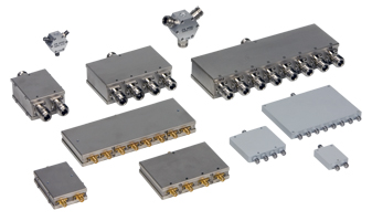
A large-scale local oscillator distribution system, such as a phased array radar test system, is a typical application for this unit. Notice that we will only cover power splitting in this blog post, not power mixing, since the two applications have somewhat different specifications. Before we look at potential options, we need to think about the performance metrics we’ll need one at a time.
Insertion Loss: For a LO distribution splitter, this is typically the most critical spec. An N way power split would have a loss of at least log2(N)3 dB by law (of conservation of energy). As a result, an 8-way power split with excess circuit losses would have a minimum loss of 9 dB. Determine how much output power is needed and how much noise is appropriate to determine where amplifiers should be mounted to compensate for circuit losses. In general, if you put them in earlier, you’ll be able to use less, but your production power will suffer as a result.
Isolation: This is the standard figure of merit for a power divider, but it may not be as relevant in this case. An N-way power divider’s two non-adjacent output ports would normally have strong isolation only from circuit losses. When looking at the isolation for the PD4-0140, for example, we can see that the average isolation from ports 1-2 or 3-4 is about 22 dB, whereas the isolation between all other ports is usually better than 30 dB.
The isolation spec is also eased by the fact that in power splitting applications, particularly at a single frequency like a LO, there is little penalty for poor isolation as long as the loads are relatively well matched. If the loads are not well matched, the reflected waves will corrupt adjacent channels; however, if the loads are well matched, the signals will match at all points and no power will be transmitted from one channel to the next. I assume that if your input return losses are less than 12 dB, isolation will not substantially boost your signal propagation.
Phase Balance: In the majority of LO delivery applications, phase balance is a must. This is a shame, because, as we’ll see later, maintaining phase balance in a functional form factor adds a lot of cost to the circuit. The problem becomes much simpler if no phase balance is needed. We aim to maintain a score of at least 5 across all outputs.
Return Loss: Return losses, including isolation, may be major or just a slight addition to the insertion loss. We aspire to be less than 15 decibels since this solves a lot of problems.
Along with insertion loss, the most closely related elements are size, form factor, and cost. If the form factor is fully negotiable, a compact, low-cost power divider with low insertion loss can be created. If the form factor must be a block of metal with SMA connectors equally spaced over one side (as is normally the case), the size increases significantly, as does insertion loss and cost.
This is the best choice if the bandwidth is adequate. Since the bandwidth disadvantage of a Wilkinson is the isolation, and LO splitting applications usually need low loss and phase balance, this is still possibly the best option when bandwidth is not appropriate. Also out of band, Wilkinsons have low loss and phase balance. In a power splitting application, the Wilkinson, unlike the resistive power divider, is preferably lossless. Only the fabrication tolerance of having the microstrip lines the same length limits the phase balance. Also, since no power is dissipated in the isolation resistors, the power handling of a Wilkinson power divider used as a splitter is very high. Why don’t we make N way Wilkinson power dividers if Wilkinson power dividers are so good for LO power distribution?
To begin with, Marki Microwave is unique in that it provides three-way Wilkinson power dividers. The complexity of laying out a three-way Wilkinson power divider is the reason for this. Although the circuit diagram is simple, the layout is extremely difficult. One of the reasons we don’t give 3 way power dividers above 26 GHz is that edge coupling can cause havoc.A branched line segment of two way power dividers is used to create four-way power dividers. This is fairly easy because all we have to do is copy our two-way power dividers three times onto the circuit and then link them with microstrip lines. Over and above the basic design, we do some optimization to increase the return loss and isolation, but that’s about it. But why not make an 8-way power divider out of it?
As an example, let’s build an 8-way X-band power divider. From 8 to 12 GHz, a single segment Wilkinson based at 10 GHz can provide better than 15 dB of isolation.With the splitting losses, the insertion loss increases, but otherwise, this design looks pretty much as you’d expect it to, with reasonable output across the band.But there’s a problem: this isn’t a physical circuit. There is no lateral isolation for the connectors along the housing’s face. To turn male connectors, they need 0.350” of separation, and we prefer at least 0.440” to allow a wrench to turn them. If we have 0.440” of separation, our 8-way power must be at least 3” along one side to be practical. Since the active power divider parts are quarter wave, or 0.218” at 10 GHz, we now have a power divider that is about 1” long and 3” tall, which is an uncommon aspect ratio.
Low-frequency losses in a low-loss microstrip line are on the order of.2 dB/inch, whereas losses in coaxial cable are on the order of 0.02 dB/inch. Microstrip loss is caused by a combination of basic per-unit length loss and additional loss due to bends and curves in practise. The connectors are the most common cause of coaxial cable losses. In practise, connector losses are less than those induced by microstrip bends, so coaxial cable is the preferred interconnect.
Standing waves on the coaxial cables between each power divider cause the return loss ripple in the eight-way power divider above. The length of the cable may be changed to some degree. While step matching requires that each section have the same cable length, different sections may have different cable lengths.
There are a range of other advantages to using a coaxial cable assembly. The change in layout is instantly evident, as power dividers can now be stacked or arranged in three dimensions in any way. It also saves resources and energy, as interconnections take up the bulk of the space in a branched power divider. This results in a big, costly, difficult-to-fabricate, and difficult-to-test aluminium housing.
Surface mount LO delivery follows the same trend as connectorized: it all comes down to scale. Integrating multiple surface mount power divider sections without surface mount transitions, which normally limit the performance of our surface mount components, can result in some improved performance. The complexity and reliability problems associated with mounting and installing such a large board, however, will overshadow any benefits. However, we do not suggest using the PD-0530SMG to conduct LO power splitting functions below 5 GHz because it will work out of band with reduced isolation.
Customers should buy our off-the-shelf power dividers (even out of band) and have their own phase matched cables or microstrip transmission lines between the parts for higher order power splitting. This allows for the least amount of damage, the cheapest price, the most layout versatility, and the smallest size solution possible.
Do you have a concern about design or fabrication? David and John are available to assist. Now is the time to visit the Eravant Technology Support Center and “Ask an Engineer.”